Inleiding

Gebruik deze handleiding om het logic board in een MacBook Air 2019 te vervangen.

Let op: de Touch ID-functie zal niet meer werken na het vervangen van het logic board. De originele Touch ID-sensor van de MacBook is in de fabriek exclusief gekoppeld aan de T2 chip op het logic board en zonder Apple's propriëtaire kalibreerproces zal zelfs het overzetten van een ander origineel logic board naar je MacBook Air geen Touch ID-functie herstellen.

Als je het logic board vervangt, moet je dus een reeds gekoppelde Touch ID-sensor installeren om de Touch ID-functie te behouden.

  1. 4a1VSQBgdQXAZah2
    • Je zult, voordat je met deze procedure begint, de Auto Boot-functie van je Mac uit moeten schakelen. Auto Boot schakelt zich in als je het scherm van je MacBook opent en kan per ongeluk worden geactiveerd tijdens het demonteren van je laptop. Gebruik deze handleiding of volg de ingekorte instructies hieronder om Auto Boot uit te schakelen.

    • Schakel je MacBook Air uit en haal deze van de oplader voordat je met deze reparatie begint. Sluit het scherm en draai de laptop om zodat deze met de onderkant naar boven wijst.

    • Gebruik P5-schroevendraaier om de volgende schroeven te verwijderen:

    • Twee 7.9 mm lange schroeven

    • Twee 7.1 mm lange schroeven

    • Zes 2.6 mm lange schroeven

    If the first thing you do is disconnect the battery, is it really an issue if you don’t (or can’t) disable auto-boot?

    maccentric -

    I agree, why disable Auto-Boot when the lid is closed and the battery is disconnected immediately? – I've never had an issue since 2016 when the feature was introduced.

    stevebsiegel -

    On my machine, the longest two screws were in the corners, while the other two long screws were in the middle. Perhaps previous service in the past had them replaced into the wrong place? In any case, the longest screws do seem to fit in either place. I guess 0.8mm is not very much of a difference. Seems like poor design if they could have used one size of screw.

    johann beda -

    Just did one, and it also had longest screws in the corners.

    maccentric -

    Just did another, and the long ones were in the middle. Definitely poor design and quality control.

    maccentric -

  2. 4Kra6VLGEa3eGmd6
    • Duw je vingers tussen het scherm en de onderste behuizing en trek deze omhoog om de onderste behuizing van de MacBook Air los te maken.

    • Verwijder de onderste behuizing.

    Das geht etwas schwer, da das Unterteil mittig noch von 2 Druckverschlüssen gehalten wird.

    facebook -

    translated and true:
    This is a bit difficult because the lower part is still held in the middle by 2 pressure fasteners.

    Tom -

    Are there any suggestions to removing the pressure fasteners more easily?

    Drea Mastromatteo -

    I used a suction cup to lift up the cover. I mean those to lift up an iPhone display. Worked like charm.

    Juergen Stawska -

  3. xVJrmDjjKX3L1VEp
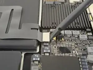
    • Trek de tape die over de batterijaansluiting heen zit ver genoeg los om de batterijaansluiting bloot te leggen.

  4. NZT3TL4hoGyeLE6L
    NZT3TL4hoGyeLE6L
    XZ2jGZmJoO1c5OHn
    • Gebruik een spudger om de batterijaansluiting uit het contact op het logic board te schuiven. Zorg dat je de aansluiting parallel aan het logic board uit het contact trekt.

    Before the battery can be fully disconnected, the battery disconnect button needs to be held down. There is a gold button just above the battery socket, along with a small LED much like the 12” machines. Once this has been held down and the LED has switched off it is safe to remove the battery.

    Aaron Dalziel -

    This seems like an important step?

    maccentric -

    Also, seems like this should be done after the battery is disconnected, not before? Otherwise, wouldn’t the battery re-charge it?

    maccentric -

    What if the white LED dosent light up after pressing the yellow button again?

    Iron05 -

    I just performed this repair on my late 2018 mac air. I did click the gold button but saw no LED illuminated or otherwise. Question- after reassembly does the button get pressed again to connect the battery? Please clarify if this button is to be pressed and if it needs pressing again after the repair.

    All said - I pressed again after the battery connector clicked, assembled the back and all worked perfectly. The original issue was one dead port (no charge, no communication). The battery charge lightening bold icon was acting funny too. Genuis bar guy in Naperville said it was likely a logic board too. But it was not. The port was apparently confusing the logic board with regards to the charge function. Thanks Adam for saving me $440 and sending my computer back to Apple. I am 71 yrs young - who says an old dog can’t learn new tricks with good training!!

    William Lane -

    I didn't see Aaron's comment before completing the battery replacement. Afterwards, the computer would not turn on despite multiple SMC reset procedures. Upon double-checking the comments I see the importance of pressing the gold button. I pressed the gold button before disconnecting the new battery, then pressed it again after reconnecting for good measure. Computer booted!

    It would be good of iFixit to add this important step as most people probably don't open up every single comment on (seemingly) simple steps.

    Corey Matsumoto -

    Seconding Corey's comment. If paid more attention to the comment section, I would have avoided 15-30 minutes of panic. (BTW I did not notice any LED, but the golden button was easy to find).

    Lorenzo Sorbo -

    Where is the gold button? I replaced my battery and my laptop will not start

    Candace Williams -

  5. mCpNcwDmVvCIexvU
    mCpNcwDmVvCIexvU
    WCiJUh1bJboPNur2
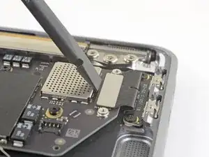
    • Gebruik een T3 Torx-schroevendraaier om de twee 1.4 mm lange schroeven die de beugel over de trackpadaansluiting bevestigen los te schroeven.

    • Verwijder de beugel over de trackpadaansluiting.

    My machine used T4 screws

    johann beda -

    Me too! I tried with T3 and it wasn’t working.

    Rose Alshuaibi -

    I stripped my screws trying to get them out with a t3 driver...

    Aubrey Corcoran -

  6. Sw6VN6VuYRYAnW2T
    Sw6VN6VuYRYAnW2T
    iGLvdxo4pDlVZOh6
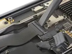
    • Gebruik het platte einde van een spudger om de kabelaansluiting van het trackpad uit het contact omhoog te duwen.

  7. 2ANOeBCRlLS1Elpu
    2ANOeBCRlLS1Elpu
    gVBNK32AwYwuWQFx
    hRm4xZQXbIkkT4O5
    • Schuif de punt van een spudger onder de speakerkabel en duw deze in een rechte beweging omhoog om de speaker los te koppelen.

    • Als je de aansluiting los hebt gekoppeld, schuif je het platte einde van je spudger onder de kabel om deze te scheiden van de lijm die het aan het logic board bevestigt.

    I think step 15 was a mistake because it’s a repeat of step 10.

    Ryan R -

    Yeah, the speaker is already removed at this point.

    Jason _ -

    el punto 15 queda anulado. se realizó en el punto 10.

    E. Parra -

  8. IHRbrlPXF2JApiqk
    IHRbrlPXF2JApiqk
    LyZ1foqy1wvBlOiv
    • Gebruik een T3 Torx-schroevendraaier om de twee 1.3 mm lange schroeven die de beugel over de USB-C poort aansluiting bevestigen los te schroeven.

    • Verwijder de beugel over de USB-C poortaansluiting.

    There is no need to remove the logic board!!

    Skip steps 16 through 28 and go to step 29 to release the trackpad cable from the battery. then follow steps to 30 through 33 to release the battery. The battery can be removed by slipping it counter-clockwise under the trackpad cable. The new battery can be slipped in place in the same way.

    Much easier!!

    josephgray -

    Agreed. Took me a minute to realize that I had to slide the top right screw bracket between the logic board and the case to get enough clearance for the rotation. Many thanks.

    w98fxr -

    Removing a few of the logic board screws allowed me to get the to right screw bracket under the logic board to give enough clearance as w98fxr mentioned.

    johann beda -

    This can be done, but it's very tight. Still, beats removing the logic board and the possibilities of breaking something in the process.

    maccentric -

  9. M3RvYGtmREQuaLZ2
    M3RvYGtmREQuaLZ2
    B6AMphVrIvwKpisH
    • Gebruik het platte einde van een spudger om de kabelaansluiting van de USB-C poort omhoog te duwen en deze uit het contact op het logic board te verwijderen.

    please reconsider removing the logic board and and usb-c connector as is recommended in the prior step. i had a very difficult time reconnecting the usb-c connector

    Mario Obejas -

    It should be cautioned that this connector is very easily bent, meaning a bend in the length of the metal surface you press against to reconnect (or pry against for removal). Once bent it becomes very hard to establish a good connection.

    James Tropauer -

  10. BjgmhIFsgtdRtuUi
    BjgmhIFsgtdRtuUi
    hgUoCSOomRaZZNMa
    XNTm2JBIuDLHFUKi
    • Gebruik een spudger om de kleine sluitklem op de ZIF-aansluiting van de geluidskaartkabel omhoog te wippen.

    • Schuif de kabel van de geluidskaart uit de ZIF-aansluiting.

  11. RK65AOeFDCjfyyWv
    • Trek de zwarte tape die over de kabelaansluiting van de ventilator heen zit geplakt los.

  12. EvCAoAoChgdZSUpP
    EvCAoAoChgdZSUpP
    VORkbyxUw5mQoLXP
    EBqFtxhhx5MFDscb
    • Gebruik de punt van je spudger om de sluitklem op de ZIF-aansluiting van de ventilatorkabel omhoog te duwen.

    • Schuif de ZIF-aansluiting van de ventilatorkabel uit het contact.

    There may not be a locking flap. If not, just pull the fan cable out of the ZIF connector.

    rmilton -

  13. tXgZY3PV2kPaADlE
    tXgZY3PV2kPaADlE
    WAgCyw6YIrvC3RQH
    • Gebruik een T3 Torx-schroevendraaier om de twee 1.4 mm lange schroeven die de beugel over de antennekabel bevestigen te verwijderen.

    • Verwijder de beugel van de antennekabel.

    These are T4 screws

    Richard Arnett -

    The MBA I just finished with were T3. I'm fairly confident with my tools as I recently updated/upgraded nearly my entire set with WiHa. I should also mention the many tools acquired from iFixit over the years have all been were exceptional lasting years. There's no doubt iFixit would have been my source but a close friend went to work for WiHa. His discount(s) & being motivated to help him was a major impact. For anyone not having such an advantage IMHO tools from iFixit are one of the best values anywhere. Let's not forget; buying from iFixit will also help to push "Right to Repair" forward. Here in Minnesota Right to repair ALMOST PASSED. Many believe it will become law during the next session! I can't tell you how proud this would make me. I would obtain as many service manuals as possible and post them all online!!! What a great dream...

    admin -

  14. SIwpML6D2V1THnvW
    SIwpML6D2V1THnvW
    HSbt4VrCJOZJWJeX
    vMkn5IqQ1LgQrMRK
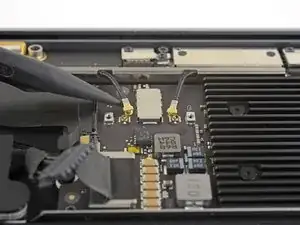
    • Steek de punt van een spudger onder een van de antennekabels, zo dicht mogelijk bij de aansluiting. Duw de kabel vervolgens recht omhoog om de kabel los te koppelen.

    • Herhaal dit bij de andere antennekabel.

    Be SUPER SUPER CAREFUL pulling off the gold WiFi antenna connectors! As described, use the spludger to press up the black cable just behind the metal connector. I tried to ping them off from the bottom of the gold connector where it clips into the socket on the motherboard and ended up pulling off the SMD sockets from the motherboard - huge and costly mistake that will probably render it useless.

    Neale Whyatt -

  15. JwduCSLFH2CcraAQ
    JwduCSLFH2CcraAQ
    kTylWJvDOGiAPbQS
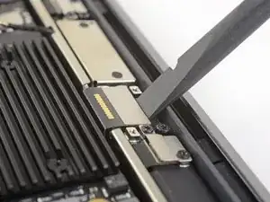
    • Gebruik een T3 Torx-schroevendraaier om de twee 1.5 mm lange schroeven die de beugel over de schermkabelaansluiting bevestigen te verwijderen.

    • Verwijder de beugel over de schermkabelaansluiting.

  16. cELhRfbeZrcbMPps
    cELhRfbeZrcbMPps
    kHkPDOnxWduTqHLa
    • Gebruik het platte einde van een spudger om de schermkabelaansluiting omhoog te duwen.

    How do I reconnect display connector??

    Kris Queck -

    Just align the plug section of the display flex with the socket on the logic board and gently press it in until it locks in place. Do not force it but just ensure it’s correctly aligned before pushing it into the socket.

    Peter Newman -

    Pro tip: You can remove the two T5 screws on the LCD connector side (located to the right of the display connector and to the left of the heat shield). From there, tilt the whole skinny LCD board towards the logic board connector and gently pinch the connector in to the socket. Before laying the skinny board back down, screw in the shield from Step 15 so it doesn’t pop out of the socket again.

    jason4 -

  17. 6TXbngaNJybXtDKP
    • Gebruik een T4 Torx-schroevendraaier om de volgende schroeven te verwijderen:

    • Eén 5.5 mm lange schroef

    • Drie 2.6 mm lange schroeven

    • Twee 1.9 mm lange schroeven

    These are T5 Torx driver screws

    Richard Arnett -

    Need torx 5 AND torx 4 driver here ;)

    Marcel Popp -

    During re-assembly be soft when screwing in the logic board because those antenna plugs in Step 14 are quite awkward to pin back into their sockets and there is little leeway in the cables; to make this task a little easier in Step 14, secure the logic board loosely right up against the near outside edge; after re-connecting all the cables in Steps 16-9, return to Step 17 to firm up the logic board screws.

    Andrew Gordon -

    This tip was a huge help, hate these cables lol

    Konrad Anderson -

    The 5.5 mm screw goes into a hexagon standoff which may come off with the logic board being sanswiched beteen the 5.5 mm screw screw and the standoff like happened to me. Just something to be aware of. It also has a black rubber bumper over the screw which was not mentioned at all. It pulls straight off to give access to the screw.

    Peter Newman -

    On my board I needed to use T6 for all the screws except the rubber bumper for which I used a T7. I have a full set of small Torx drivers and tried for the best fit.

    jeffyouell -

    T5 fit best is all the screws on my machine

    johann beda -

  18. eHXdqWRQTLhS4rxV
    • Verwijder het logic board.

Conclusie

Vergelijk je vervangende onderdeel met het originele onderdeel — het kan zijn dat je meerdere onderdelen mee over moet zetten of beschermlagen voor de lijm moet verwijderen voordat je het nieuwe onderdeel kunt installeren.

Om je toestel weer in elkaar te zetten, volg je deze instructies in omgekeerde volgorde.

Breng je e-afval naar een door R2 of e-Stewards gecertificeerde recycler.

Ging je reparatie niet zoals gepland? Check dan ons Antwoordenforum voor hulp bij het oplossen van je probleem.

Adam O'Camb

Lid sinds: 11/04/15

212588 Reputatie

Een commentaar

Consulta , para este modelo el cambio de pasta disipadora es diferente a modelos anteriores, es factible colocarle una HY510 HEATSINK?

A lo que voy es que yo desmonte un equipo, y lo revise y veo que la pasta esta medio seca.

Arturo Lugo -