Inleiding

Deze handleiding laat zien hoe je de oplaadpoort van een JBL Xtreme verwijdert. Deze handleiding vereist soldeervaardigheden.

  1. pPDPdbHHNTLbBn1q
    • Zoek de naden naast de 'voetjes' aan de onderkant van het apparaat.

  2. RQvvxOw2BSPi2gUb
    RQvvxOw2BSPi2gUb
    xu4RHpACjQ3H11eK
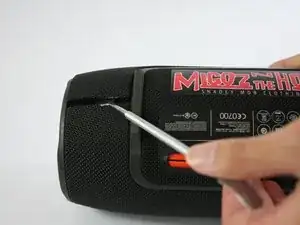
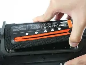
    • Gebruik de metalen spudger om de rand van de naad los te wrikken en op te tillen. Het deksel wordt op zijn plaats gehouden met plastic drukknopen die een ploppend geluid maken wanneer ze worden losgehaald. !!Begin met de achterste helft, hierdoor komen TWEE schroeven vrij die moeten worden verwijderd voordat de voorste helft wordt opgetild.

    Start with the back half, this will expose TWO Screws that need to be removed before lifting the front half.

    MrMindlink -

    Yes, the fact needs to be added that two screws need to also be removed to get the cover off. One side snaps off but the other is attached with two screws.

    Terry Kraft -

    %#*@^@. I ripped the plastic things apart. Should have red the comments first. &&^&.

    brobarongg -

    same here ;D just grabbed some glue and hope it will stick :D

    Patrick Tippner -

    Vorsichtig die Kante hochhebel, wo der Reissverschluss ist. Da ist die Hülle gesteckt. Die andere Seite hat Schrauben die man lösen sollte. Ansonsten zerstört man zu Beginn die Befestigung der einen Seite.

    Roland Bürger -

  3. hY4NHUuftxrAdXZm
    hY4NHUuftxrAdXZm
    nQ4DCYQvDELRulLT
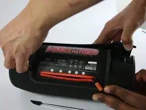
    • Voor het eerste deel van de hoes: trek voorzichtig de randen van de hoes terug, draaiend langs het scharnier tegenover de openingsnaad die op de tweede foto wordt geïllustreerd. Kunststof drukknopen houden het deksel op zijn plaats.

    • Voor het tweede deel van de hoes: er moeten 2 schroeven bij de naad worden verwijderd. Eenmaal verwijderd, zal de behuizing volledig loskomen zonder te forceren.

    Hello Where can I get a replacement cover?? Mine is damaged.

    juan.rey19 -

    Did u ever find it they sell the covers?

    jorgetovar698 -

    Careful with this step, my JBL Xtreme case was also held in place by wo little srews !

    Arthur Lecharny -

    It feels like you are “breaking” the cover, but in fact it seems to have a kind of “bending point” near the top of the cover by the exterior controls. Watch for the two screws to remove.

    Terry Kraft -

    There is two screws holding the cover at its other end beside the plastic snaps

    Nader Belaid -

    %#*@! broke one of the little snaps near the 2 screws. still holds tight though.. be careful when pulling them out. Also, don’t forget the screws

    Mike -

    Die beiden Schrauben befinden sich jeweils neben den Füßen des Geräts. (Ein Foto von den beiden Schrauben wäre sehr hilfreich!)

    RTFM -

  4. qKkh3iRZdMwORuRO
    qKkh3iRZdMwORuRO
    QvXktYsfUptfyYPP
    FH2BgGTb5ERw3Luh
    • Draai de zes 9,75 mm kruiskopschroeven los die de basradiator op zijn plaats houden.

    • Drie van de vijf buitenste schroeven zijn aangegeven in de eerste afbeelding en de zesde binnenste schroef is aangegeven in de tweede afbeelding.

    This was the most difficult part for me. The screws are pretty tight, I needed a larger screwdriver to get them out.

    Terry Kraft -

    A PH1 or PZ1 Philips screw driver worked for me. For re- assembly it helps to place the speaker on the side with the other end facing down. That way you can exert more force. I would start with tightening all screws part way only and when they are all in place tighten them all the way (including the inner screw).

    RTFM -

    Achtung, die Bassstrahler sind mit dem Gehäuse über zwei “Klebedichtungen” verbunden. Diese müssen beim Zusammenbau wieder eingebaut werden.

    Carsten Schultze-Hartmann -

    Die Dichtung war bei mir nicht geklebt, sondern in die dafür vorgesehene Rille eingelegt. Sie ist mir beim Entfernen des Bassstrahlers zwar gerissen, ich konnte sie jedoch mit einem spitzen Kunststoffspachtel wieder in die Rille legen. Beim Zusammenbau muss man darauf achten, dass die Dichtung nicht herausrutscht. Am besten die Seite mit der Dichtung nach unten halten.

    RTFM -

  5. hcbSAWpYTwYerNJw
    hcbSAWpYTwYerNJw
    yD1VyWXCPbT3l1Eu
    lSQYERFWiGiEunGe
    • Nadat de schroeven zijn verwijderd, komt de basradiator gemakkelijk los.

    • Beide radiatoren zijn identiek. Herhaal indien nodig bovenstaande stappen op de tegenoverliggende radiator.

    where can i buy these parts mate?

    troy yerbury -

    Where can I buy the bass radiators independently?

    Daryl Duliep Hernandez -

    Ich empfehlen, erst den 7. Schritt auszuführen. So kann anhand der Kabel feststellen welcher Bassstrahler entfernt werden muss!

    I would recommend to do the 7th step first. So can determine, based on the cable, which bass radiator must be removed!

    Android Robo -

    Wo kann ich den die Ersatzteile kaufen bassstrahler und ein hochtöner???

    Sven Muelle -

    Schritt sieben zuerst ist eine grandiose Idee, erspart einiges an Nerven.

    Benni Basisch -

    die Linke Seite wie auf dem Bild ist die richtige. Dahinter findet man die Platine mit dem Anschlussstecker für den Akku. Somit sollte eigentlich 1ne Seite reichen.

    Roland Bürger -

    So war es auch bei mir. Nur die linke Seite (von unten gesehen), also die Seite auf der der Zug vom „Reißverschluss“ endet, wenn er geöffnet ist, muss geöffnet werden. Dann kann man sich die Demontage der anderen Seite sparen!

    RTFM -

    attention, il y a entre chaque radiateur et le corps principal un joint très fin, tout autour. Il n'est pas collé et se détache facilement, l faut faire attention à le déplacer le moins possible, et à ne pas l'écraser, surtout si on retourne l'enceinte pour enlever l'autre radiateur (ce qui est inutile, il n'y en a qu'un à enlever pour accéder au connecteur de la batterie

    Gugu Fafa -

  6. Cd5plbuJ1KQOdPqH
    Cd5plbuJ1KQOdPqH
    J3fsRoQBRXXVmbsM
    aCb2UuloymCw5K1w
    • Zoek en ontkoppel de drie stekkers die op deze afbeeldingen worden aangegeven.

  7. 3Hg1g2TUxSmNkDPB
    3Hg1g2TUxSmNkDPB
    3oUXO5EXQYNRaRSB
    • Koppel de drie poorten los van de vorige stap.

    • Een pincet kan handig zijn om dieper in het apparaat te reiken.

  8. v24sFfciZPnlIVw1
    v24sFfciZPnlIVw1
    1WOeYaCFGAoU3gad
    DkWQ1M2atNPJcrKj
    • Zoek de drie kruiskopschroeven in het ritsvak en draai ze los.

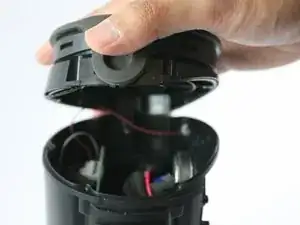
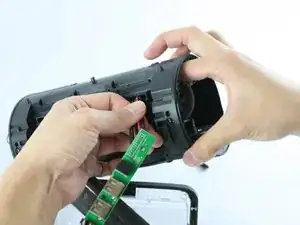
    • Trek het ritspaneel los van het apparaat.

  9. y5XwNDL3xPVB144d
    y5XwNDL3xPVB144d
    D3XwTeie2grwxlaP
    JRrGorjZUqB3inJA
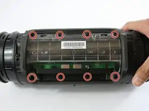
    • Onder het ritspaneel zitten nog acht kruiskopschroeven. Schroef ze los en til voorzichtig het batterijdeksel op.

    • Pas op dat u de kleine witte lintkabel die het batterijklepje met de rest van het apparaat verbindt, niet beschadigt.

  10. HSvlOqwaoPvCaFHG
    HSvlOqwaoPvCaFHG
    CuMU3ciOoJJ2pVeZ
    • Draai de drie 11,88 mm kruiskopschroeven los die in de afbeelding zijn gemarkeerd.

  11. YUinKAMgxLQH3YkC
    YUinKAMgxLQH3YkC
    qaYgiW5XPyTGesGG
    • Trek de hulpkaart naar buiten.

    • Er is schuim dat de draden bedekt, waardoor het moeilijk is om de hulpkaart te verwijderen. Neem de tijd voor deze stap.

    hello, thanx for the great guide . i got a defekt xtreme and opened it like you write in your guide ,because my one doesn´t show any reaction when i plug power in. no charging or anything . as i opened it i saw that the capacitor on the last foto was burned out .

    and than the big surprise , my auxilary board is not the same like yours . it´s 100 % a original xtreme and everything is simillar but on my bord is a 8 leg IC soldering -place. sorry for my bad english , it´s very difficult to explain . if anyone outthere can help me i send pictures from my board ,and you will be surprised that it has on the board a place for a IC ..

    ch. geyer -

  12. xLmWAxPVpDlG3Eag
    xLmWAxPVpDlG3Eag
    sGlv6enSBON2wVRf
    BF5yN5iDNa3wcNBL
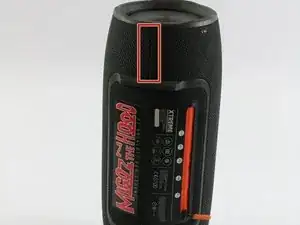
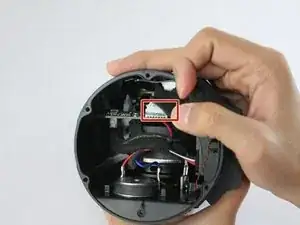
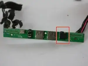
    • De eerste afbeelding markeert de oplaadpoort.

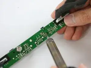
    • Zoek 6 metalen pinnen gemarkeerd in de tweede afbeelding en gebruik een soldeerbout om de pinnen los te koppelen.

    Die Ladebuchse hat nur 3 Lötstellen…!

    Ihr redete von der Ladebuchse aber Lötet die 3,5mm Klinke…

    llPͥeLͣ Lͫell -

    The final two pictures are incorrect. They show the pins for the Aux in, not the Coaxial Barrel charging jack. You can tell by the cord with the foam around it. In the first pic it's on the far side of the board in comparison to the charging jack, but when flipped, it's bear it. This is incorrect. You can also tell by the protruding tips of the jack when flipped, the larger one is the charging jack, but the flipped picture shows them soldering the pins pf the smaller jack. Please update, this may be causing many people difficulty.

    If you want to hire me to write these articles instead in a precise and thorough manner, please reach out in a comment.

    Regards,

    David

    David -

Conclusie

Volg deze instructies in omgekeerde volgorde om je apparaat weer in elkaar te zetten.

Benny Huynh

Lid sinds: 15/02/17

1992 Reputatie

2 commentaren

Please I have a JBL XTREME that sparks each time I plug it. What could be the cause

morris_ugwoke -

Hi. Can someone advise where a replacement charging port can be sourced? I.e., so I can desolder the existing one and solder a new one in its place. The existing one is badly corroded so the unit won't charge. Thanks Andy

Andy R -