Inleiding

Let op: verwijder altijd eerst de stekker uit het stopcontact voordat je gaat demonteren.

Als de machine niet meer kan worden ingeschakeld, kan de voedingskaart defect zijn. In de meeste gevallen zijn de componenten van de schakelende voeding doorgebrand. De onderdelen zijn niet duur en het is de moeite waard om te proberen ze te repareren. Je moet echter wel goed kunnen solderen/desolderen, we hebben a guide.

De onderdelen zijn vrij eenvoudig te vinden in elektronicawinkels, in het bijzonder heb je een weerstand van 47 Ohm, 3W, een spoel van 1mH en een IC LNK364GN nodig.

  1. gGp2mPtSZjLFUs4E
    • Haal de stekker uit het stopcontact!

    • Verwijder alle losse delen zoals het waterreservoir, de opvangbak en de zetgroep.

    • Draai de machine zo dat de achterkant naar je toe wijst.

    • Verwijder de vijf T20 Torx Security-schroeven.

    • Eén klein obstakel: deze schroeven hebben een pin in het midden, dus de torxschroevendraaier moet een gat hebben (dit zijn de Torx Security-bitjes).

    Screwdriver must have a hole? What does that mean? Is it a standard Tx20 bit?

    Kevin -

    No, it is a TR20 Security Bit, which really has a hole (if you look to the star shape) . See TR10 Torx Security Screwdriver

    VauWeh -

    Bits from iFixit are equipped with it.

    VauWeh -

  2. BnoacoHxc6HQr1YS
    BnoacoHxc6HQr1YS
    RiGlr1amJrHguDl2
    • Til het achterste paneel van het koffiezetapparaat af.

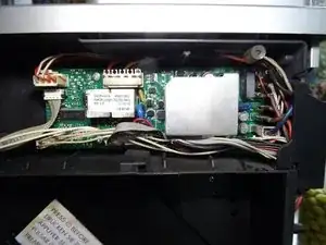
    • De volgende onderdelen zijn meteen zichtbaar:

    • Koffiemolen

    • De pomp

    • De stromingsmeter

    Sehr gute Anleitung. Die Security Schrauben der Rückwand können auch durch normale Kreuzschlitzschrauben ersetzt werden. Natürlich mit gleichen Abmessungen. Es erleichtert bei späteren Reparatur Arbeiten die Werkzeuge Auswahl , da überall Kreuzschlitzschrauben verbaut sind.

    Willi Greubel -

  3. dm44GwGUppKOfExQ
    • Verwijder de achterzijde van het toestel: schuif het deksel aan de kant van het waterreservoir een klein stukje naar achteren en verwijder het.

  4. IbqYOc51nDQFIBDc
    • Het voedingsbord bevindt zich achter het deksel. Het bord is bevestigd door middel van vier schroeven in de hoeken en verbonden met een aantal kabels.

    • Duw de kabels een beetje opzij en draai de vier kruiskopschroeven los.

  5. DNdRO2KyS6DX2xw1
    DNdRO2KyS6DX2xw1
    Qu2UqPyHG2MnFp3J
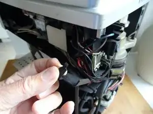
    • De kabels hebben veel verschillende connectoren en zijn bijna onmogelijk door elkaar te halen. Let vooral goed op waar de kabelschoenstekkers zijn aangesloten, en neem eventueel foto's van alle stekkers en aansluitingen.

    • De platte kabelschoenstekkers kunnen gemakkelijker worden verwijderd als je het zwarte klepje rechts in de hoek van het apparaat wat naar de zijkant tilt.

    • Til het voedingsbord er een paar centimeter uit.

    • Maak alle verbindingen voorzichtig los. Sommige zijn extra bevestigd met vergrendelingen die je eerst moet wegduwen of indrukken.

  6. POoXkHANm5pDHUVj
    POoXkHANm5pDHUVj
    wHwsGTyDUNNjkFPr
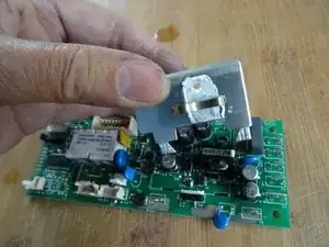
    • Hier is de voedingskaart. De aluminium koelplaat zit alleen met drie lipjes vast aan de achterkant van het bord. Gebruik een tang om de drie lipjes recht te maken en til de koelplaat eruit. Denk eraan dat een triac vastgeklemd zit aan de koelplaat.

    • Zorg er bij het monteren ervoor dat je voldoende warmtegeleidende pasta hebt aangebracht.

  7. uHvLw4dH4GVuXNUQ
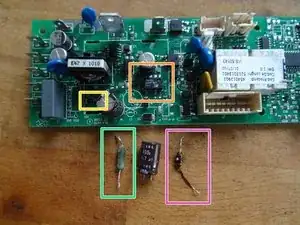
    • Dit zijn de belangrijkste onderdelen:

    • R55: Weerstand, 47 Ohm, 3 W

    • L1: inductie 1mH

    • U1: geïntegreerde schakelaar IC LNK364GN

  8. pDZDVCur4ZoCgFNw
    pDZDVCur4ZoCgFNw
    mJEkXkWvJ1omD3XB
    • Desoldeer eerst deze drie onderdelen. Gebruik een desoldeerpomp en/of desoldeervlecht. Het desolderen van het IC is lastig omdat het een SMD-versie is. Het is makkelijker als je vooraf ook de condensator C3 desoldeert; je kunt eventueel ook voorzichtig de pennen van het IC afknippen.

    • Controleer de componenten:

    • De inductie L1 van deze printplaat was duidelijk defect, hij was zwart, gele kralen waren uitgezweet, de weerstand was veel te hoog, hij zou rond de 3 Ohm moeten liggen.

    • De 47 Ohm weerstand R55 was oneindig - dus niets kan meer werken.

    • Het IC LNK364 was waarschijnlijk de oorzaak van het defect, tussen de twee pinnen met de grote opening zou de weerstand een paar megOhm moeten zijn, het was slechts een paar Ohm.

    • Controleer voor de zekerheid ook diode D1 (indien geïnstalleerd); deze mag maar in één richting geleiden. Als hij defect is, vervang hem dan door een 1N4005. (kathode, d.w.z. min in richting L1)

    • Soldeer alles weer vast en neem eerst een kop koffie... andere componenten kunnen ook defect zijn...

Conclusie

Voer de stappen in omgekeerde volgorde uit om het apparaat weer in elkaar te zetten.

VauWeh

Lid sinds: 19/10/15

268312 Reputatie

21 commentaren

Hallo die Anleitung, passt im wesentlich auch zur ECAM 23 450S - die Platine sieht etwas anders aus - man muss kein Kühlblech demontieren, die Bauteile tragen die gleichen Nummern / Bezeichnungen. Nach dem Wechsel läuft unsere Minna wieder. Danke - auf die nächsten 12 Jahre.

A. Weber -

Freut mich, Grüße.

VauWeh -

Hallo,

ESAM 3600, die Platine ist auch anders die baustein Bezeichnung ist gleich.

Reparatur hat dank Anleitung bestens geklappt.

Danke

LG Dieter

Dieter Stach -

Interessante Info, danke. Freut mich, dass es geklappt hat.

VauWeh -

Thank you for sharing! Had the same problem with mine, thanks to your guide I could repair the board and the machine works well as before. Nice!

Robert

Benedikt Robert Hajas -

I'm glad to hear that. Another machine saved. Repair is war on entropy!

VauWeh -

Below the two white relays there's a component on Q1. Can you or anyone else help me find out what that is? Mine is blown and unidentifiable, I assume Q2 is probably the same but Q2 is unpopulated on my board so I have nothing to compare with.

John D'oh -

Is there really a relay? Perhaps this page helps, they tried a reverse engineering for ESAM.

VauWeh -

Thank you for the reply. Yes what I refered to is the two white relays, that usually have a sticker with the board part number and software version on top of them.

In the meantime I may or may not have found some useful information for me and anyone else needing to diagnose and repair these boards. There are a some variance between machine models, but that appears to mostly be software and which components are populated, not so much different components.

In my case, it seems Q1 and Q2 is an SOT-23 packaged P-channel FET. Component CHT2301PT (this is discontinued) or TSM2301. Alternatively, PNP Resistor Equipped Transistor: PDTA143ET.

I'm pretty sure it's a not allowed to share scematics or links to such material on Ifixit. But lets instead imagine for a moment; some hypothetical Oogle might reference something called "delonghi_ecam_21.116_21.117_22.110_parts_schema_pcb" as a source of... useful information :)

John D'oh -

@prollie do you mean the document on the bottom of this page DeLonghi ECAM Series Nice find. It'll be a lot easier to keep it here than to have to go through a search engine and all that stuff. This way people can focus on helping you instead of hunting for it :-) You got the iFixit Guru @vauweh working on it so you know it'll be resolved :-) Repair is War on Entropy!

oldturkey03 -

@prollie @oldturkey03 Well - this fault ist unknown to me and I appreciate the link! I hope that replacing the parts is the right solution. Otherwise there ist another possibility (for european users): When I had issues like yours, they did the job.

VauWeh -

I have same problem with my coffee machine. I have made quick lookup with schematic and multimeter and everything looks fine expect U1 - LNK364GN. it seems strange to me that only U1 would be at fault and it would be enough to replace only U1. Why is it destroyed? Any suggestions?

Jaromir Hurek -

Your post and question is unclear. "Have the same problem"

= Will not power on?

"it seems strange to me that only U1 would be at fault and it would be enough to replace only U1"

= you replaced this IC, and that was enough to fix it? If not, are you certain that this is the only failed component? Or are you unsure if there could be more rhat you may have missed?

It's not guaranteed always the case, but this IC very often fail together with the big 3W resistor and the choke (?) right next to it. These can fail from power spikes, so there's also fuses to check. Do also inspect the traces(!) thoroughly on both sides. In a few instances, I have seen some of the small traces on the back of the board completely burnt off; detached from the board substrate and curled up.

Depending on how bad, that can take some time to fix but it's not complicated. If a trace is severely blown like this and you reconstruct it, remember to also check that none of the vias along that trace have also gotten burnt off.

John D'oh -

Beim Zusammenbau ist mir aufgefallen, daß es eine Verwechslungsmöglichkeit gibt: Die beiden 2-poligen weißen Stecker mit der Bezeichnung 16 und 17 ,an der linken Platinenseite (im Kontakt J6 und J12) könnten vertauscht werden, alle anderen Steckverbinder sind eindeutig zuordenbar. Wie ist es richtig , Stecker 16 oben an J6, und Stecker 17 unten an J12 oder gerade andersrum?

Günther -

@guenther13523 Im Moment weiß ich das auch nicht, es steht aber wahrscheinlich hier, ganz am Ende der Link zum Service Manual.

VauWeh -

J6 ist der Stecker zum Thermosensor, da müssten so steife weiße Kabel hinführen.

VauWeh -

Thanks for this really great share! I've just successfully used the instructions to bring my machine back from the dead :-)

All the guidance in checking the components was spot on. The only thing I deliberated over was the replacement inductor as the guidance said it should be around 3 ohms. Obviously matching the inductance is a given, but I'm not sure how important the resistance value is? I got kinda stuck with either matching the resistance but not the appearance, or different resistance and matching the appearance. I went for the latter with resistance around 13 ohms and it still worked fine.

To help people in the UK this is what I ordered from ***https://cpc.farnell.com/***

RE04280 MOR03SJ0470A19 RESISTOR, 3W 5% 47R 10 off

SC18635 LNK364GN-TL AC/DC CONV, FLYBACK, -40 TO 150DEG C 2 off

FT01436 B78108S1105J INDUCTOR, AXIAL, 1000UH 5 off

There's a few extras in there just in case as the parts are cheap (the small order handling charge was as much as the components)

Which came to £7.76 delivered

Jon Clear -

Ich habe auch eine Delonghi Dinamica, ECAM 350.55.B.

Folgendes ist passiert:

Maschine angemacht, sie bewegte das Mahlwerk usw. Und plötzlich hörte ich ein lauten knall und es fiel die Küchensicherung raus und die Maschine ließ sich nicht mehr einschalten nachdem ich die Sicherung wieder eingeschaltet habe. Ist hierbei die hier beschriebene Anleitung die richtige oder wäre es eher was anderes was dazu führt das die Maschine nicht mehr an geht?

Danke im voraus

D M -

Ich denke nicht, dass diese Anleitung ausreicht. Das muss mehr sein. Um die Ursache zu finden, muss das Gerät geöffnet werden, vielleicht sieht man irgendwo Verbrennungsspuren?

VauWeh -

Da sich die Mühle eingeschaltet hat, denke ich eher an den Pumpenanschluss, sie wird mit 220V betrieben. Im Programm der Maschine wird zuerst das Mahlwerk eingeschaltet und dann die Pumpe.

Martin -

Das kann sein. Stecke doch einfach die Zuleitungen zur Pumpe ab und schaue mal, was passiert. Sei aber vorsichtig, Netzspannung!

VauWeh -