Power networks/Guidelines/Substations
.jpg)
Power substations are facilities designed to support transit of power through grids. They host several kind of equipment used to measure, transform voltage or change frequency, switch or compensate energy coming from multiple power lines that terminate within their premises.
In OpenStreetMap, substations are, above all, visible and significant features in the landscape.
Understanding substations helps model energy systems and support power capacity planning.
These guidelines complement existing tagging documentation and focus on good practices, combining multiple tagging concepts in a consistent and responsible effort to describe complex facilities.
Substations are industrial sites, typically closed to the public and posing serious risks (including death risk) such as electrical hazards, heat, or exposure to chemicals.
Information gathering on-site should always be done safely and in full compliance with local regulations and warning signs. You must never enter restricted or hazardous areas, and this documentation does not encourage or expect you to trespass fences or gates under any circumstances.
Covered features
This documentation is intended to map visible parts, properties and equipment of all power substations, both for transmission and distribution networks.
It includes proper perimeters, power lines terminals and significant equipment.
Substations can be located outdoors, indoors within dedicated buildings or other structures, or inside street cabinets in the case of smaller installations.
How to find substations
To locate power substations that may need mapping, you can try the following approaches:
- Check around power generation facilities (such as nuclear, thermal, hydroelectric, wind or solar plants). Substations are almost always located nearby. Verify whether all surrounding substations are already mapped.
- Look near urban areas. Substations are commonly found on the outskirts of towns and cities, where they serve as key nodes in regional electricity distribution.
- By tracing power lines that are already mapped, you can often identify missing substations or other infrastructure elements that need to be added. Every overhead power line (power=line) must begin and end at a defined structure:
- a substation
power=substation, - a line management structure (e.g.,
line_management=*, - or an emergence point where cables transition from underground to overhead.
- a substation
How to map
Common principles
Substations mapping is an optional and technical practice of OpenStreetMap contribution.
Some local rules and practices may apply for some part of what is described there. It is recommended to have a look to country dedicated pages on Power_networks to get more information.
Please consider them carefully as to not disturb some specific undergoing work in the country your are visiting.
Substation role
Substations actually hosts several functions and has got different roles in the power grid. What is found inside or the purpose for which a substation has been built can be described in OpenStreetMap with the help of substation=*.
You may answer some simple questions to find the most suitable value for the facility you want to map. Here are some basic ones:
- Is this substation dedicated to deliver power to a particular industrial facility nearby? If yes, you may have a look to
substation=industrial. - Is this substation intended to connect a particular power plant to the power grid? If yes, you may be looking for
substation=generation. - Is this substation dedicated to deliver power to the public distribution grid, operated by the distribution operator in the area? If yes, it's about
substation=distribution - Is this substation big enough to connect several major transmission lines, ensuring transit between several other substations in the transmission grid? If yes, just use
substation=transmission.
Neighboring substations may also be a source of inspiration and it's useful to maintain consistency of choices for similar substations on a given power grid.
Outdoor substations
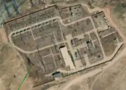
We will start with the substation you have just discovered, with no feature mapped in OpenStreetMap.
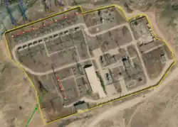
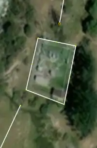
In the following section of this documentation, we will use a substation in Tajikistan, 572748333![]() 572748333, with coordinates 38.6984372, 69.7094241.
572748333, with coordinates 38.6984372, 69.7094241.
Outdoor substations are often large fenced facilities hosting technical stuff over several acres. They can be landmarks both in landscape and on aerial imagery.
As open facilities, most installed equipment is visible from outside and can be documented.
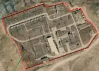
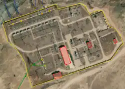
Closed perimeter
Outdoor substations should be mapped as areas ![]() and tagged with
and tagged with power=substation.
Several areas can be grouped in a multipolygon relation if necessary and then the substation's attributes should be put on the relation and not on every single area.
You can consider adding additional tags like usual voltage=*, name=*, and operator=*.
At first glance and according to we've already covered above, this substation allows transit between major power lines, including via transformers that step up/down voltages, so we can deduce with certainty that it's a substation=transmission.
If the substation is enclosed by a fence or wall (e.g. for restricted access), this barrier should also be mapped accordingly with barrier=*.
| Single fenced perimeter | Several areas |
|---|---|
|
|
barrier=fence
|
Perimeters grouped in a multipolygon area.
Example: 1382580387 |
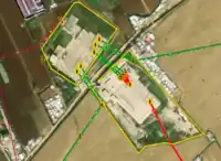
Line ends / portals
Lines leading to substations often stop on portals. Portals consist of long solid or lattice structures composed of legs and horizontal beams to anchor the conductors.
It is convenient to map them as ways. This offers a supplementary structure to properly organize lines on the map around the substation.
For the sake of mapping accuracy, ending lines inside substations areas increase the map relevancy and allows consumers to explicitly know which line is connected and which isn't.
Mapping power portals
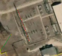
To begin, add portals when they are visible. You can find them directly on aerial imagery or deduce their position based on their shadows.
Portals should be drawn as a ![]() with
with power=portal, with their ends aligned with the shadows of the portal’s legs. A typical portal consists of two legs, a horizontal beam, and supports a 3-phase line.
It's also useful to add along this way as many nodes as legs on the portal. This makes it easier to count them and avoid confusion with other features.
You will get more detailed information and useful guidelines directly on the power=portal page.
| Substation view | Detailed view |
|---|---|
|
|
| Portal drawn as ways | The nodes should align with the portal's support poles. |
Ending lines on the portals
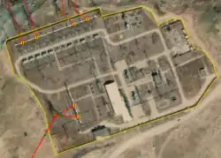
When portals are properly identified in the substation, you can finish each line at the appropriate portal.
Simply connect each power line in the middle of the horizontal beam, as shown below.
| Substation view | Detailed view |
|---|---|
|
|
| Connect the power lines to a |
Tag this power=insulator.
|
Considering splits
A power=line with circuits=1 and cables=3 should be connected to a single power=insulator ![]() .
.
It is not useful to map every individual insulator and split 3-phase lines into 3 separate ways in front of the portal.
In case you have to end a multiple circuits power line (for instance 2 circuits with 6 cables or more), it should split in several separate 1-circuit lines. Mind adding line_management=split on the tower where the circuits split.
Each circuit should be connected to its own insulator as shown above.
Notes: In large substations, there may be more portals than active power lines. In such cases, do not tag power=insulator on unused portals.
A power line can enter a portal either in a straight line or at an angle—both are acceptable.
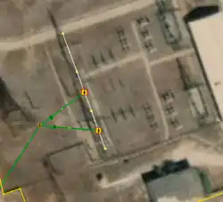
Portals as nodes
As an alternative it is also possible to map portals as nodes ending power lines.
It's useful when aerial imagery quality is too low to identify properly legs and power lines bays.
In this case, tag it with power=portal and connect the power line directly to it.
Do not add a power=insulator tag in this situation. Like shown below:
| No portal | Portal as node inside substation area |
|---|---|
|

|
Buildings
Technical buildings located within the substation perimeter should be mapped as areas and tagged with building=yes, building=service or building=industrial.
These buildings typically host service equipment, switch gear, or protection systems.
Mapping them helps to get the substation actual visual footprint as some buildings may be tall (transformers maintenance hall for instance)
Transformers
Transformers are found in substations and are intended to change voltage levels between incoming and outgoing lines.
Transformers are generally easy to identify in aerial imagery: they appear as large rectangular blocks, often metallic and distinct from other equipment, with lines connected to them.
Most substations contain at least one transformer and thus handle several voltage levels.
As a good practice, check that the transformer's primary and secondary voltages match the voltage levels of the switch gear zones and lines it's connected to.
Transformers are often located beside switch gear zones (see below), and are sometimes separated from each other by firewalls or blast walls (barrier=wall) to prevent fire propagation.
Transformers should be mapped as ![]() and tagged with
and tagged with power=transformer.
If known, consider including additional tagging:
- The voltage with
voltage:primary=*,voltage:secondary=*... - The amount of phases they process with
phases=*. - The frequency at which they operate, usually
frequency=50orfrequency=60depending on your area, but may be different for train traction or industry facilities, for instance. - Their role in the facility with
transformer=*. - Their
operator=*,name=*orref=*. - And even more complex properties like
windings=*orwindings:configuration=*.
Each key page provides guidelines on how to use that tag correctly.
| Substation view | Detailed view |
|---|---|
| Draw transformers as a |
Bus bars / switchgears
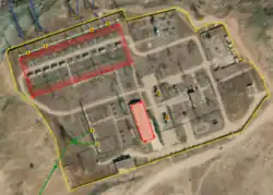
As the name suggests, switch gears are places where power is switched with the help of power=switch.
Each switch gear operates at a single and given voltage and is composed of one or several bus bars with lines bays leading to them.
We map large switch gears as areas surrounding bus bars and switching equipment when outdoor or directly on containing building when indoor with building=industrial.
In most cases, switch gear zones are visually identifiable in satellite imagery as areas with dense and organized electrical equipment.
You can use power=switchgear and voltage=* for that.
If a technical building is located between the incoming lines and the transformers, it likely contains the switchgear. In this case, the building’s polygon should be tagged accordingly with power=switchgear.
When aerial imagery is good enough, it is possible to map bus bars with dedicated ways.
Bus bars are arranged in straight lines and located between the incoming/outgoing power portals and the transformers (when present).
They form the core connection hub for switching and routing current across voltage levels or transmission paths.
Bus bars should be mapped as ways ![]() and tagged with
and tagged with power=line, line=busbar, cables=* and voltage=*.
Roads

Substations often include paths and roads that allow technicians to move safely between equipment.
They should be mapped as ways ![]() and tagged with
and tagged with highway=service and access=private
Natural cover
As substations can be large areas, grass and trees can partly cover the ground where no asphalt or gravel are required.
You can map those parts with standard natural=grassland and trees with natural=tree.
Indoor substations
Indoor substations are located inside buildings, dedicated or not, intended for design or space constraints.
As we don't see as many equipment as in outdoor ones, we could document the purpose or the building and the most prominent parts when possible.
Visible transformers, switches or bus bars should be mapped as described in the outdoor substation section upside.
Lines ends / terminals
An indoor substation located in a building requires to connect lines coming from the outdoor to the equipment inside.
It is slightly a sensitive point as the link between outdoor and indoor is supported by the building walls with particular mechanical and insulation constraints.
Points on which outgoing power lines are anchored to the substation building are mapped with power=terminal.
Dedicated switch gear halls
Although indoor substations are located indoor to save space, larger ones may be composed of several buildings with particular roles.
As mentioned in the outdoor substations section, switch gears hosted in dedicated buildings are mapped with building=industrial + power=switchgear + voltage=*.
Quality control
Coming soon
Reference works
Some proposals have been reviews since 2010 on this particular subject:
- Substation refinement
- Power transformers extension
- Substations as nodes
- Transformers classification refinement