Power generation/Guidelines/Solar plants
Covered features
This documentation offers practical guidance for mapping solar power infrastructure, with a focus on the following types of plants : photovoltaic, thermal power, thermal heating.
The aim is to ensure consistent, high-quality mapping, especially during organised editing. Accurate tagging helps support research, planning, and energy transition projects.
Note: This documentation does not cover small residential rooftop installations on commercial buildings and individual homes.
Photovoltaic plants
Technology: Photovoltaic plants (usually abbreviated with PV) generate electricity by converting sunlight into energy using solar panels.
These plants include:
- Ground-mounted PV: with panels on racks on the ground;
- Floating solar (FPV): mounted on a floating structure in a body of water;
- Agrivoltaics: when combined with agricultural use.
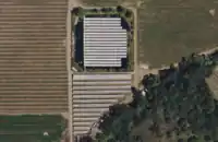
In satellite imagery: They can be easily distinguished by their size, location and the layout of the panels.
Grid connection: Most PV plants are connected to the electrical grid through power lines and an on-site electrical generation substation.
| Type of plant | Ground-mounted PV plants | Floating solar plants | Agrivoltaic PV plants |
|---|---|---|---|
| Illustration | 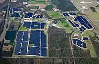
|

|
-AGRO-Photovoltaic_power_station_Heggelbach-05ASD.jpg)
|
| Satellite Image | 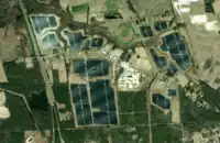
|
|
|
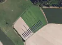
| Name of the project | Warsaw Solar Facility, North Carolina, USA | FPV in Niente Winery, Napa Valley, California, USA | Agri-Photovoltaic system Heggelbach, Baden-Württemberg, Germany |
| Coordinates | 35.0025998, -78.1274571 | 38.4219656, -122.4085575 | 47.8536938, 9.1365793 |
Thermal power plants
Technology: Solar thermal power plants concentrate sunlight by using mirrors or lenses, heating a fluid that drives a turbine to generate electricity.
These plants include:
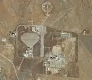
- Parabolic trough systems: long curved mirrors focusing sunlight onto receiver tubes;
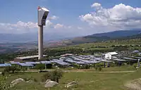
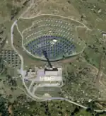
- Solar power towers: mirrors, also called heliostats, that concentrate sunlight onto a central tower;
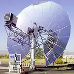
- Stirling engines: parabolic dishes focusing light onto a thermal engine.
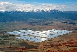
In satellite imagery: They can often be recognized by large mirrored fields, a central tower (in tower systems), and associated power blocks or thermal storage tanks.
Grid connection: Like other thermal plants, they are connected to the electrical grid via a substation and high-voltage power lines.
| Type of plant | Parabolic trough systems | Solar power towers | Stirling engines |
|---|---|---|---|
| Illustration | 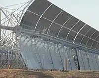
|
|
|
| Satellite Image | 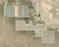
|
|
|
| Name of the project | Mojave Solar Project, California, USA | Solar tower of the Thémis solar power plant in Pyrénées-Orientales, France | Dish Stirling system by SOLO Motoren in Almería, Spain |
| Coordinates | 35.0025376, -117.3043138 | 42.501389, 1.974167 | 37.0948168, -2.3612343 |
Thermal heating plants
Technology:
Solar thermal heating plants use mirrors or collectors to concentrate sunlight and heat a fluid, which is then distributed directly for heating purposes, such as residential heating, industrial processes, or hot water supply.
These plants include:
- Parabolic troughs or flat-plate collectors arranged in fields ;
- Central receiver systems with thermal storage for continuous heat supply.
- Solar furnace: large arrays of mirrors concentrate sunlight onto a focal point.
In satellite imagery:
Most can appear similar to solar thermal power plants but lack a turbine block and high-vltage grid connection.
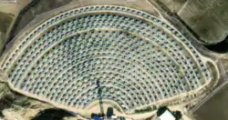
Solar furnaces are recognizable by their semi-circular or fan-shaped mirror fields focused toward a central tower or receiver, often located near research or industrial buildings.
Grid connection:
Solar thermal heating plants are typically connected to heat distribution networks rather than electrical infrastructure.
Some may include an on-site distribution or industrial substation. It brings in medium- or low-voltage electricity to power equipment, lighting, and control systems.
An important distinction here is that unlike photovoltaic or solar thermal power plants, solar thermal heating plants do not export electricity to the grid, and therefore have no large high-voltage transmission lines leaving the facility.
| Type of plant | Parabolic troughs or flat-plate collectors | Central receiver systems | Solar furnace |
|---|---|---|---|
| Illustration | Coming soon | Coming soon | 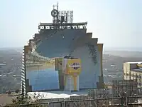
|
| Satellite image | XX | XX | 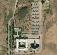
|
| Name of the project | XX | XX | Solar Furnace, Parkent, Uzbekistan |
| Coordinates | 41.3146523, 69.740568 |
How to map
Among other facilities, we could use this ground solar photovoltaic power plant as an example to map common premises and generators.
Thermal power and heating situation may be addressed with other locations.
Common principles
Solar plants mapping is an optional and technical practice of OpenStreetMap contribution. Some local rules and practices may apply for some part of what is described there. It is recommended to have a look to country dedicated pages on Power_networks and Power_generation to get more information. Please consider them carefully as to not disturb some specific undergoing work in the country your are visiting.
Closed perimeter
Solar power plants should be mapped as ![]() and should represent the physical extent of the installation as seen on satellite imagery.
If you are certain that the same plant spans across multiple non-contiguous areas, use a
and should represent the physical extent of the installation as seen on satellite imagery.
If you are certain that the same plant spans across multiple non-contiguous areas, use a type=multipolygon relation and apply all plant-related tags to the relation, not to each individual area.
These facilities are typically enclosed by a fence or wall for security and restricted access. You can map and tag this perimeter using the appropriate barrier=*.
Tagging differ between technologies of solar power plants but the following can be used in every situation:
It is then completed in each section below.
Buildings and roads
Paths and roads inside the solar power plants should be mapped as ways ![]() . They connect internal components like inverters, control rooms, or maintenance zones. As such, they are typically only used by the staff and maintenance vehicles for technical operations, and have restricted access.
These roads and paths usually run between and around panel or mirror rows and clusters (except in floating PV plants), in order to provide access for vehicles and staff. Map any route that connects panels, generators, or technical buildings and that is visible.
. They connect internal components like inverters, control rooms, or maintenance zones. As such, they are typically only used by the staff and maintenance vehicles for technical operations, and have restricted access.
These roads and paths usually run between and around panel or mirror rows and clusters (except in floating PV plants), in order to provide access for vehicles and staff. Map any route that connects panels, generators, or technical buildings and that is visible.
Recommended tags:
When mapping:
- Trace each road accurately using satellite imagery.
- Optionally, try to properly connect them with public roads at the facility entrance (if visible), often behind
barrier=nodewhen the road crosses the fenced perimeter. - Optionally, add surface details such as
surface=gravelorsurface=unpavedwhere applicable.
How to map photovoltaic plants
When mapping a photovoltaic power plant, it's important to distinguish between:
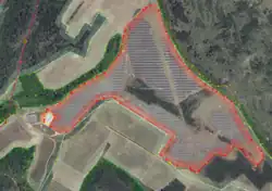
- The plant perimeter: the overall area of the solar facility.
- The individual generators: each group of panels inside the plant.
The solar plant should be mapped as an ![]() (
(type=multipolygon if needed) and the tagging completes what explain in the closed perimeter section upside:
Recommended tags:
power=plantplant:source=solarplant:method=photovoltaicplant:output:electricity=*: Add the known capacity (ex. 500 MW) if available.
Generators
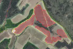
PV panels are flat surfaces that convert sunlight directly into electricity using solar cells. In satellite imagery, they typically appear as dark blue or black rectangular shapes, often arranged in long rows or grouped into rectangular clusters. They are usually tilted at a fixed angle and aligned in the same direction to optimize sun exposure.
In imagery, one can see small light-colored boxes located beside or between rows or clusters of panels. These are inverters and their role is to convert the direct current (DC) produced by the panels into alternating current (AC) used by the electrical grid.
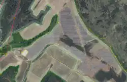
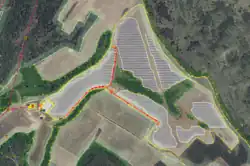
Even if anyone can map each individual panel with power=generator areas, it is recommended and acceptable to map actual hulls around group of panels, like on the example on the picture.
It is enough to perceive the difference between the global plant surface and the actual covered surface with panels, even if the hull is wider than the panels.
In the used example, we see that approximately 25% of the plant surface is not covered by panels. It's relevant to serve as an explanation of the actual output power of the plant against its whole surface.
Recommended tags:
Each mapped group of panels should be tagged separately using the following tags :
power=generatorgenerator:source=solargenerator:output:electricity=yes- Additionally, if the installed power capacity is known, you can add it using
generator:output:electricity=*=* with a value in kilowatts (kW) or megawatts (MW). generator:method=photovoltaicgenerator:type=solar_photovoltaic_panel
These tags can be applied to individual panels or to panel clusters, depending on imagery quality (see below).
When mapping:
If high-resolution satellite imagery is available, map each visible panel as a separate area (![]() ). This provides the most accurate representation of the plant layout.
). This provides the most accurate representation of the plant layout.
If the resolution is lower or if panels are too tightly packed to distinguish clearly, you can map a cluster of panels as a single area polygon instead. This is still useful for analysis and rendering.
Note: Electrical lines between panels and inverters should not be mapped, as they are not verifiable from satellite imagery.
Generation substation
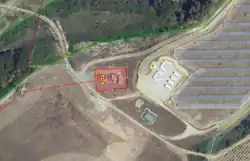
Most if not all solar PV plants have a substation on their premises, that connects the plant to the transmission grid.
This substation is usually located within or near the solar plant perimeter and may include equipment such as transformers, switchgear, portals and overhead lines.
Please refer to the Substation mapping guidelines for more information.
Recommended tags:
The following tags can be applied on the perimeter of the substation, mapped as an ![]() .
.
When mapping :
General rules on substations mapping apply here as well.
Please refer to the Substations mapping guidelines for more information.
How to map thermal power plants
Although different systems exist, solar thermal power plants usually consist of a large number of movable mirrors, called heliostats, which are mounted on ground structures and oriented to reflect sunlight toward a central receiver.
The receiver is typically a tower or a dish, also known as a concentrator, which captures and concentrates the heat into electricity.
Some thermal power plants also include energy storage tanks.
As with most power plants, you’ll also find technical buildings, service roads, and a generation substation nearby.
The solar plant should be mapped as an ![]() (
(type=multipolygon if needed) and the tagging completes what explain in the closed perimeter section upside:
Recommended tags:
Mirrors
Heliostats are flat, sun-tracking mirrors that reflect sunlight toward a central receiver. On satellite imagery, they appear as shiny square or rectangular shapes arranged in radial or grid patterns across a large area.
Note: Heliostats are not photovoltaic panels. They do not generate electricity directly but intended to focus solar rays on a focal point. They should not be tagged with =*.
Recommended tags:
On the heliostats:
When mapping:
Heliostats can be mapped as ![]() or as
or as ![]() when their outline is clearly visible.
when their outline is clearly visible.
Concentrator
At the center or focal point, you’ll often see:
- A tower receiver, often circular in shape with a bright reflection on top.
- A dish, smaller and often mapped as a single node.
They are used to transfer the heat provided by heliostats into a fluid that carries it to the generator nearby.
For sake of simplicity, concentrator and generator can be merged into a single one feature in OSM.
Recommended tags:
On the concentrator:
power=generatorgenerator:source=solargenerator:method=concentratinggenerator:type=solar_thermal_collectorgenerator:output:electricity=yes
When mapping:
Tower receivers should be mapped as circular ![]() features based on the visible base of the structure.
features based on the visible base of the structure.
Dishes can be mapped as a single ![]() located at the center of the reflective surface.
located at the center of the reflective surface.
When present, energy storage tanks can be mapped as circular or rectangular ![]() , and tagged with
, and tagged with man_made=storage_tank.
Generation substation
The following tags can be applied on the perimeter of the substation, mapped as an ![]() .
.
Recommended tags:
When mapping:
General rules on substation mapping apply here as well.
Please refer to the Substation mapping guidelines for more information.
How to map thermal heating plants
A solar thermal heating plant uses solar energy to produce heat, not electricity. Unlike photovoltaic or concentrated solar power plants, it supplies thermal energy to nearby homes or industrial processes, typically through a district heating network. Thus, they are located in residential areas or industrial zones.
The system heats a fluid (like water, oil or molten salt) using concentrated sunlight, then distributes it via underground pipes. It is not connected to the electrical grid, and therefore there is no generation substation.
Equipment often includes:
- Heliostats: as seen in the section above
- A concentrator: pipe, tower, or receiver array that collects and transfers the heat.
- Heat exchangers, pumps, and pipes located in technical buildings or underground.
- Sometimes, thermal storage tanks.
The solar plant should be mapped as an ![]() (
(type=multipolygon if needed) and the tagging completes what explain in the closed perimeter section upside:
Recommended tags:
power=plantplant:source=solarplant:method=thermalplant:output:hot_water=yesorplant:output:steam=yes
Mirrors
See illustrations in the solar thermal power plant section upside.
Recommended tags:
On the heliostats:
When mapping:
Heliostats can be mapped as ![]() or as
or as ![]() when their outline is clearly visible.
when their outline is clearly visible.
Concentrator
At the center or focal point, you’ll often see:
- A tower receiver, often circular in shape with a bright reflection on top.
- A dish, smaller and often mapped as a single node.
They are used to transfer the heat provided by heliostats into a fluid that carries it to the generator nearby.
For sake of simplicity, concentrator and generator can be merged into a single one feature in OSM.
Recommended tags:
On the concentrator:
power=generatorgenerator:source=solargenerator:method=thermalgenerator:type=thermalgenerator:output:heat=yesorgenerator:output:hot_water=yesdepending on the plant's function
When mapping:
Tower receivers should be mapped as circular ![]() features based on the visible base of the structure.
features based on the visible base of the structure.
Dishes can be mapped as a single ![]() located at the center of the reflective surface.
located at the center of the reflective surface.
When present, energy storage tanks can be mapped as circular or rectangular ![]() , and tagged with
, and tagged with man_made=storage_tank.
Quality control
Common mistakes
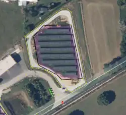
Mapping the surface of a solar power plant and its generators
The solar power plant and its barriers should be mapped as a single ![]() that includes all generators and internal paths.
Individual generators should ideally be mapped as separate
that includes all generators and internal paths.
Individual generators should ideally be mapped as separate ![]() features within the power plant boundary.
features within the power plant boundary.
| Before | After |
|---|---|
|

|
| An area tagged with only barrier=fence. A second area tagged with power=plant, that goes around the generators, but does not include paths. The generators are not mapped. | A single area tagged with power=plant and all relevant tags, as well as and barrier=fence, covering the entire facility, including generators and internal paths. Generators are mapped as separate areas. |
Reference works
See also
- UK 2019-Q3 solar power project
- Global energy monitor solar power mapping, Glint solar power mapping, Oh my grid organized editing activities